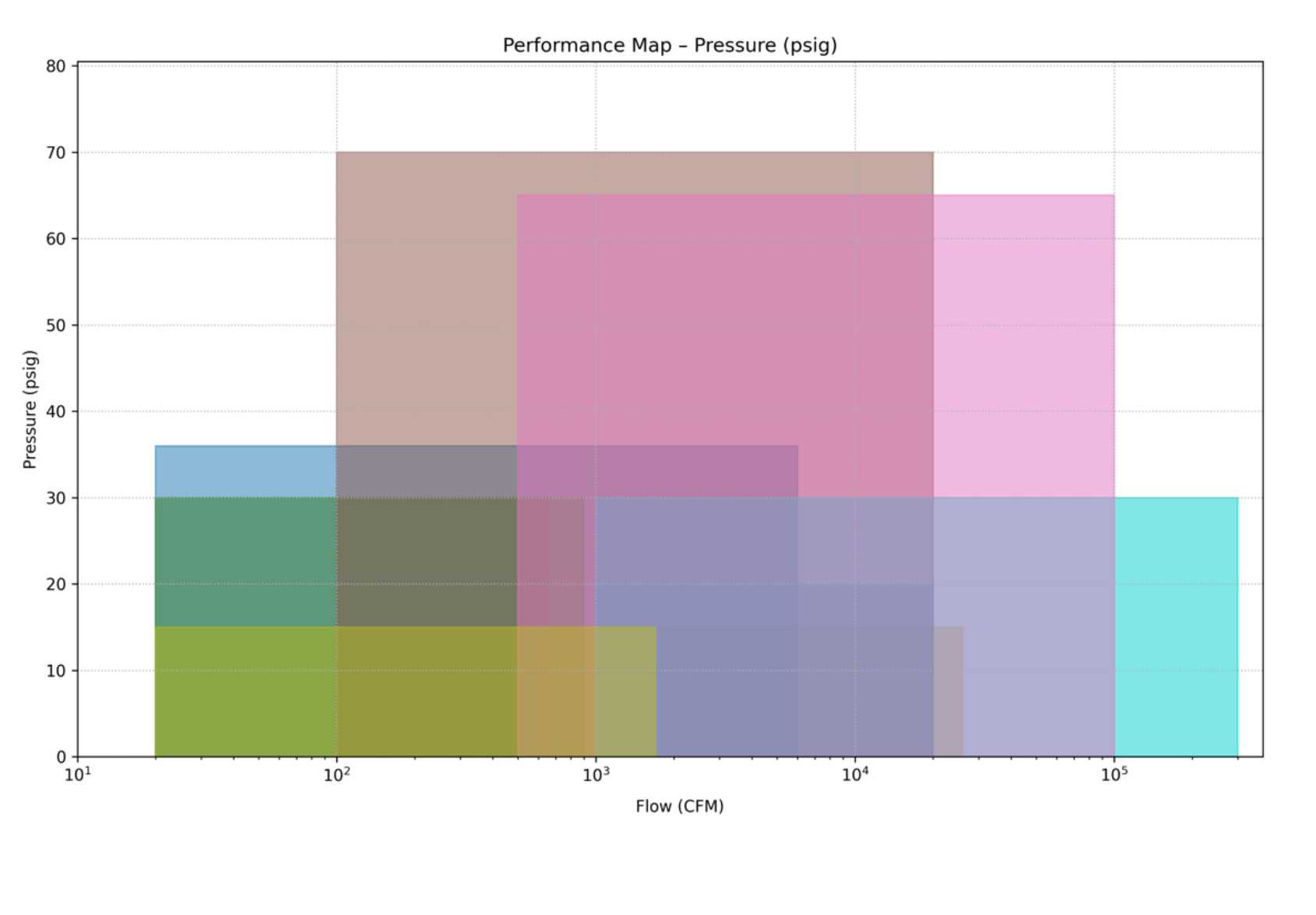
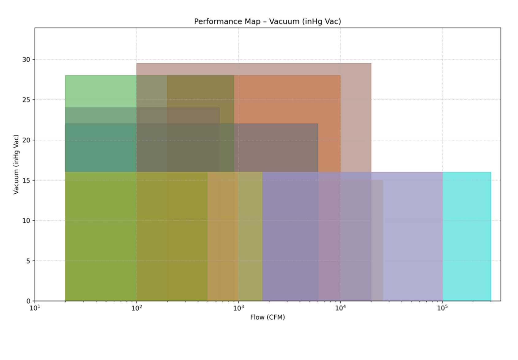
Select pressure or vacuum by clicking on one of the graphs above. Once you make your selection, use the left-hand navigation to choose a blower type.
Choose a blower type from the left-hand menu.
ROTARY LOBE
Rotary lobe blowers are positive displacement machines, commonly used for handling air or other gases up to 2 to 1 compression ratios, for either pressure or vacuum duty. These machines consist of two precision machined rotors which rotate opposite to one another, within an enclosed cylinder comprised of the housing (casing) and endplates. As each impeller passes the inlet opening of the housing, it traps a positive volume of air or gas and carries it around the housing to the discharge opening, where it is expelled.
The impellers are non-contacting, operating with minimal clearances. Impellers maintain these clearances through the use of timing gears. In addition, clearances between the impellers, housing, and endplates are held to very low values to minimize "back slipping" of the discharge gas to the inlet side, to optimize efficiency. Rotary blowers operate dry, without the need for a sealing fluid or lubricant within the process chamber. The impellers are commonly two-lobe, figure eight shaped, or three-lobe. Rotary blowers with two lobe impellers expel four pockets of air or gas per revolution, while units with three lobe impellers expel six pockets of air or gas.
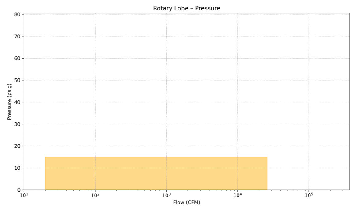
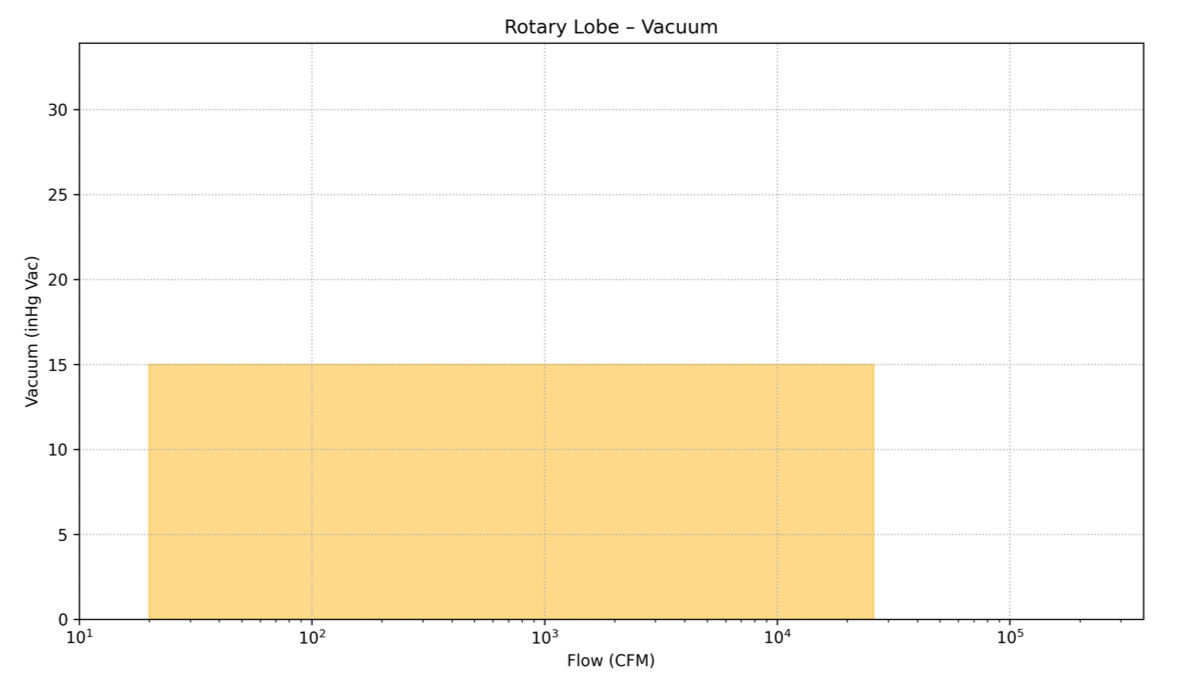
Due to their operating principles, rotary blowers will see minor variations in flow compared to changes in differential pressure or vacuum. Typical operating ranges are from 2 to 15 psig under pressure duty, though designs are available up to 20 psig. In addition, units can be multi-staged for duty as high as 40 psig with interstage cooling.
For rotary lobe technology, vacuums to 15 inches Hg are typical, though models are available as high as 28 inches Hg. Variations in internal seal designs are available for use in non-air service, where leak tight operation is essential.
Rotary lobe blowers are commonly used in the following applications:
CAGI members who manufacture this product
Atlas Copco Compressors
Gardner Denver
Hibon/Ingersoll Rand
Roots Blowers
Kaeser Compressors
MD-Kinney
ROTARY SCREW/HELICAL SCREW
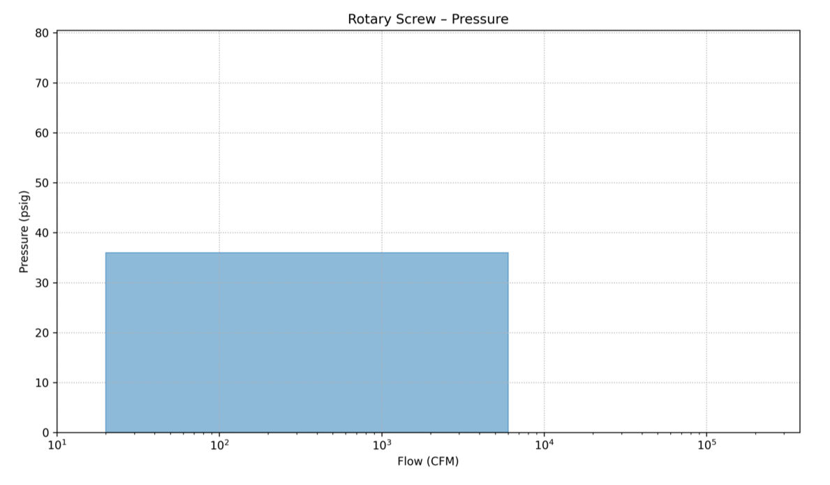
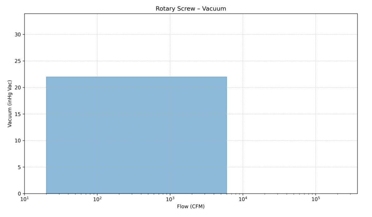
Rotary screw blowers, also known as helical screw blowers, function as low-pressure, oil free blowers (compressors) with discharge pressures up to 36 psig. The flows of rotary screw blowers are available from 20 cfm to 6,000 cfm and are available from a wide number of manufacturers. In vacuum service, the rotary screw blower can achieve vacuum levels as low as 22" Hg (v).
The rotary screw blower utilizes two intermeshing screws positioned parallel to each other inside a machined cylinder. The rotors consist of two separate precision-machined profiles: a male rotor and a female rotor. The male rotor rotates inside the cavity formed between the two flutes of the female rotor. The trapped cavity between the two rotors and the wall of the cylinder forms the compression chamber. As the rotors rotate, the trapped cavity propagates down the screw path of the rotors from the inlet to the discharge port. Unlike straight- or twisted-lobe blowers, where the airflow through the blower is perpendicular to the rotor shafts, rotary screw blowers have an axial airflow, parallel to the rotor shafts.
Rotary screw blowers have an internal compression ratio. Rotary screw blowers are typically machined to tighter clearances between rotors and housing than rotary lobe-type blowers, allowing for higher efficiency at a given compression ratio. Tighter clearances result in reduced slip (or blow-by), rotor deflection and operating temperature. Lower rotor temperature reduces thermal expansion and reduces the risk of rotor-rotor and rotor-housing contact during operation. Additionally, rotary screw blowers can achieve a higher compression ratio than rotary lobe in a single stage of compression.
Rotary screw blowers are commonly used in the following applications:
CAGI members who manufacture this product
Atlas Copco Compressors
Gardner Denver
Hibon/Ingersoll Rand
Kaeser Compressors
ROTARY CLAW
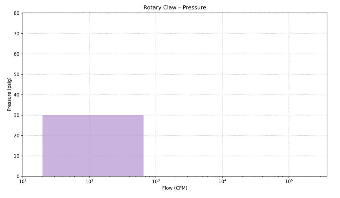
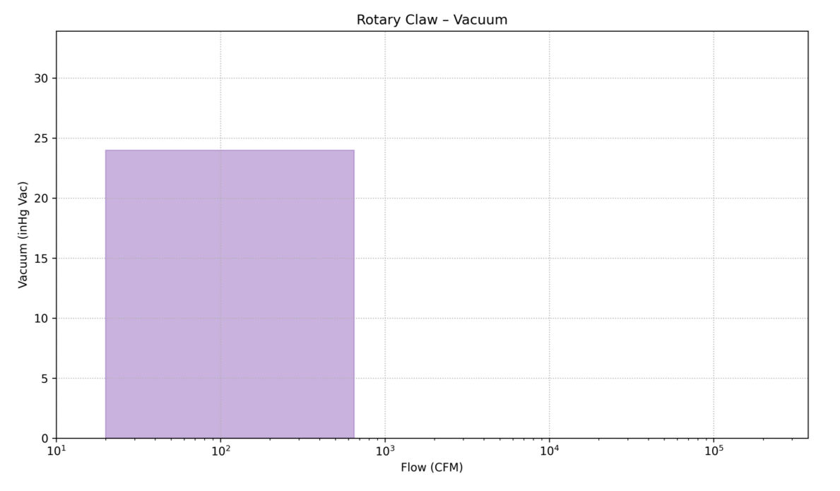
Rotary claw pumps are oil free, positive-displacement machines that can operate in pressure service up to 30 psig and vacuum service down to 24” Hg (v). The volumetric flow associated with this technology is generally 650 cfm or less. A rotary claw pump consists of two claw-shaped rotors. A drive rotor transfers power to the impellers through a set of timing gears, ensuring that the impellers do not contact each other. Extremely tight machined clearances allow the claws to maintain minuscule gaps between themselves and the cylinder during their rotation, minimizing slip. Similar to lobe-type and rotary screw blowers, rotary claw blowers employ oil lubrication for bearings and gears. Shaft seals keep the lubricant from entering the compression chamber and the high-pressure process air from pressurizing the gearcase.
Claw pumps typically are supplied as fully packaged units. Packages commonly include the claw air-end, integrated motor, inlet filter, and discharge silencer. By using variable speed motors, rotary claw blowers can be tuned to match a precise flowrate requirement. For flowrates in excess of 650 cfm, multiple claw airends can be operated in parallel.
Rotary claw blowers are commonly used in the following applications:
CAGI members who manufacture this product
Atlas Copco
MD-Kinney
ROTARY VANE/SLIDING
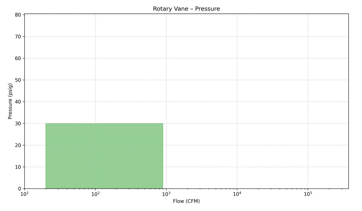
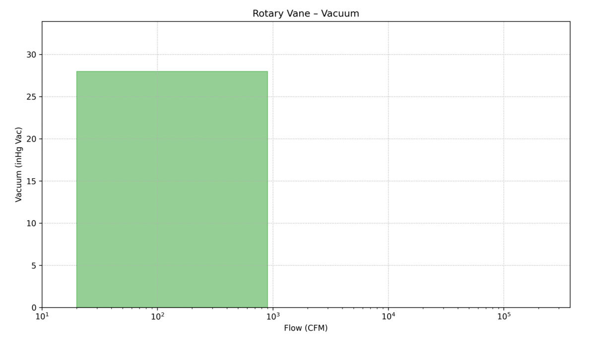
Rotary vane blowers are positive displacement machines that are available in oil free and oil injected designs. Oil free rotary vane blowers are typically used in pressure only service and have flows less than 400 cfm, with maximum pressure of 30 psig. Oil injected sliding vane blowers have flows up to 900 cfm with pressure capability of up to 24 psig with vacuum capability up to 28" Hg.
The rotary vane blower develops internal compression and utilizes both adiabatic and isochoric compression to generate system pressure. Accordingly, rotary vane blowers have efficiency and noise characteristics like rotary screw and rotary claw blowers. The rotary vane blower, also known as a sliding vane blower, consists of a housing, a rotor, and vanes as major components.
Rotary vane blowers are available as bare blowers. These types of blowers are often used in mobile transport industry applications for higher-pressure bulk material conveying and for vacuum-assisted onload and pressure-assisted offload of both bulk solids and liquids. For mobile applications, additional accessories are needed for a complete system. These accessories are oftentimes designed as a compact, fully packaged system for ease of installation on a truck chassis.
Rotary vane blowers are commonly used in the following applications:
CAGI members who manufacture this product
Atlas Copco Compressors
Fruitland Manufacturing
Gardner Denver
DIRECT-DRIVE SINGLE STAGE CENTRIFUGAL – HIGH SPEED TURBO
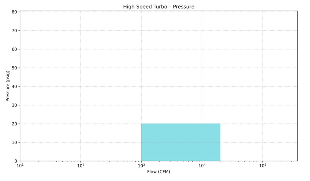
Turbo blowers utilize a single stage centrifugal air-end which is a direct-drive blower using a high-speed motor that is directly attached to the impeller shaft. These motors are variable-speed motors and can rotate from 10,000 to 70,000 rpm by varying the frequency of the power supplied to the motor.
These packaged turbo blowers driven by high-speed VFD-controlled motors are typically limited to low voltage (600 volts or less) due to the prohibitive cost of variable-speed drives on motors above this low-voltage threshold. This limits the maximum horsepower of turbo blowers to 500 hp. Turbo blowers are produced from 50 hp to 500 hp with pressure capability of up to 20 psig. The flow range for turbo blowers is from 1,000 cfm to upwards of 20,000 cfm.
Direct drive turbo blowers utilize one of two bearing technologies for the high-speed shaft: 1) airfoil or 2) magnetic bearings. Both versions are oil free and non-contact bearing technologies. The air bearing creates an air pressure film barrier between the shaft journal and bearing surface as the shaft rotates. The shaft is essentially riding on air as it rotates. The magnetic bearing uses magnetic force to suspend the shaft so that the shaft rotates and levitates inside the magnetic bearing. Both technologies allow the shaft to rotate without contacting the bearing surface.
Single stage centrifugal high-speed turbos are commonly used in the following applications:
CAGI members who manufacture this product
Atlas Copco Compressors
Kaeser Compressors
Gardner Denver
LIQUID RING
Liquid ring vacuum pumps (LRVP) work with a centrifugal liquid ring induced by an impeller offset in a pump housing. There is no mechanical contact between the moving parts, and the liquid acts like little pistons, allowing the machinery, in essence, to function like a conventional piston pump.
Upon activation, the rotor and liquid ring spins simultaneously. The rotor is positioned slightly eccentric to the center, thus dividing the liquid ring into cells. As these cells rotate, they create an airspace adjacent to the rotor’s center, and the liquid moves away from the rotor's hub, consequently producing a suction effect.
Conversely, when the cells pass the bottom, the movement redirects and forces the service liquid towards the hub, resulting in the expulsion of air from the segment—now filled with liquid and ready for a new cycle. To partition the suction and pressure sides, a flow plate and pump housing are strategically placed at the casing ends.
Continuous supply of liquid is required to compensate for the liquid discharge from the pump. In addition to providing replacement liquid, the liquid also cools the compressor gas in the pump and lubricates the mechanical shaft seals.
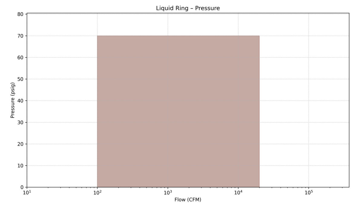
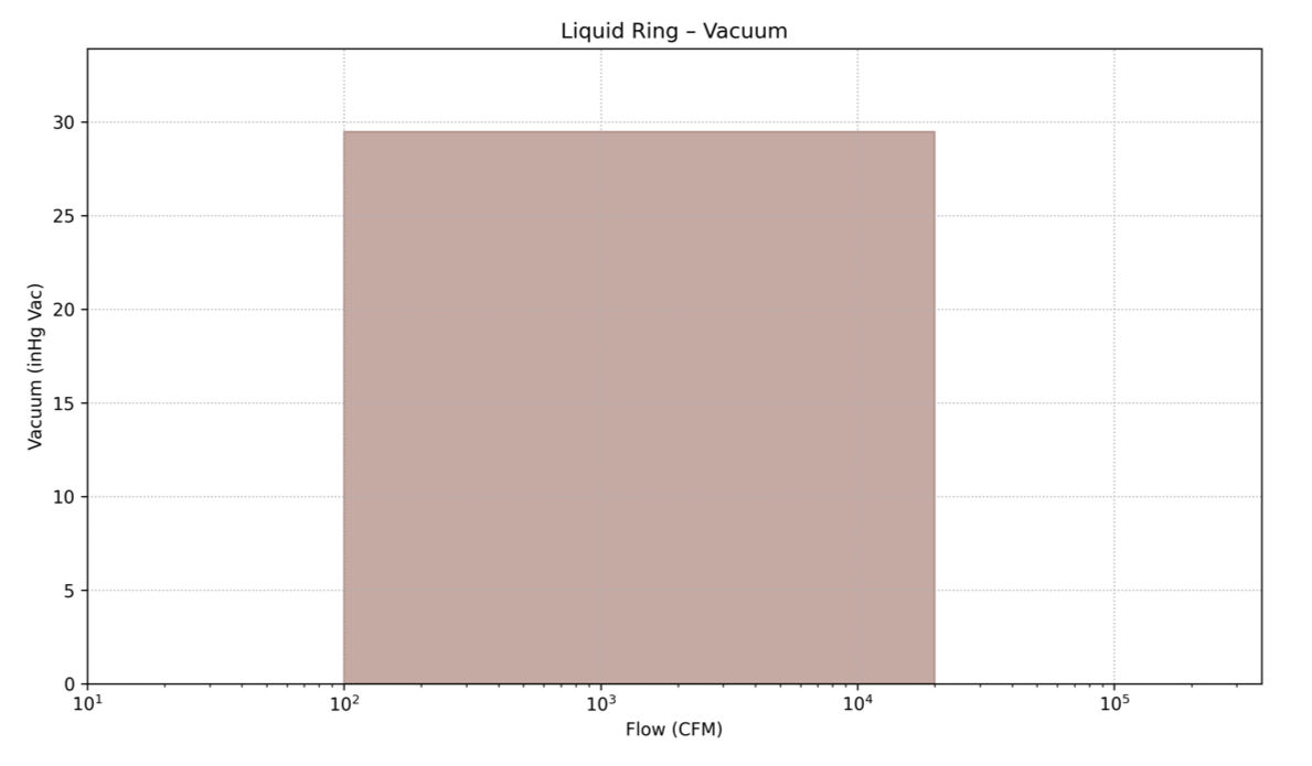
LRVPs can be supplied up to 2,000 HP with pressure capabilities up to 70 psig and vacuum levels down to 29.5" Hg. The flow range for LRVPs is from 100 cfm to upwards of 20,000 cfm.
Liquid ring blowers are commonly used in the following applications:
CAGI members who manufacture this product
Atlas Copco Compressors
Fruitland Manufacturing
Gardner Denver
MD-Kinney
SINGLE STAGE CENTRIFUGAL – INTEGRAL GEAR/EXTERNAL DRIVE
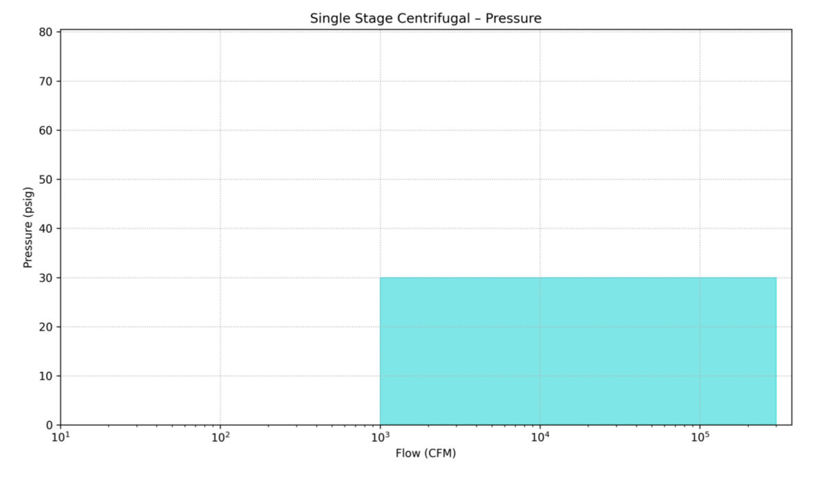
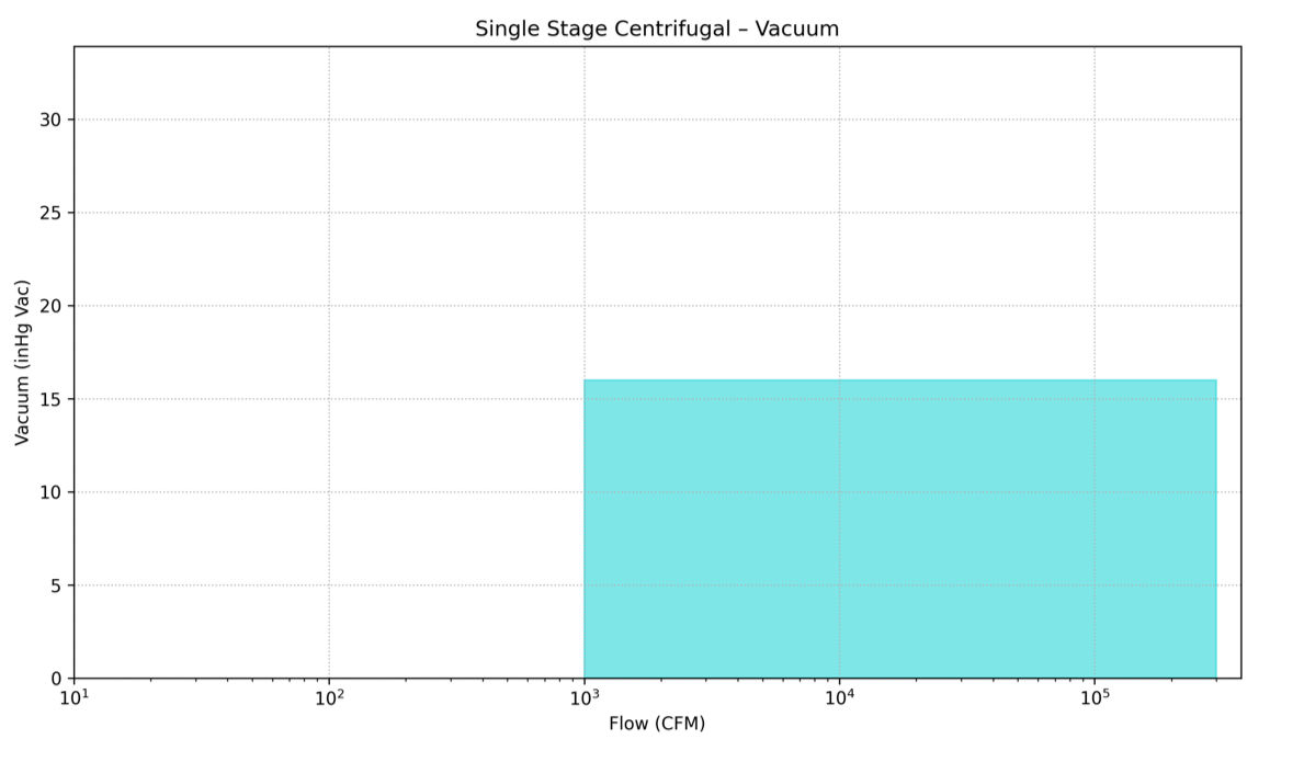
A single stage centrifugal blower is a variable flow type machine suitable for application in a wide range of gases including air up to a 3 to 1 compression ratio. The compression ratio capability is dependent upon the application conditions such as the gas being compressed, impeller tip speed, and blade geometry. A single stage centrifugal can be applied to both pressure and vacuum applications and for flows ranging from 1,000 cfm up to 300,000 cfm.
Single stage centrifugal blowers have a single radial impeller mounted within the casing. The impeller and casing materials will vary depending on the gas being handled and the pressure and temperature conditions. The application will dictate which shaft seal design is appropriate.
Single stage centrifugal blowers offer a wide operational range and can be adjusted for speed and other control features to provide high operational efficiency throughout this range.
The single stage centrifugal blowers are driven by electric motors or steam turbines. There is often a speed increasing gear required to drive the single stage impeller to the required design speed. The single stage designs that have an integrated gear box with the casing are known as integral gear.
Single Stage Centrifugal – Integral Gear/External Drive blowers are commonly used in the following applications:
CAGI members who manufacture this product
Atlas Copco Compressors
Roots Blowers
MULTISTAGE CENTRIFUGAL (WITH HORIZONTALLY & VERTICALLY SPLIT CASINGS)
Multistage blowers are available in two basic housing designs: vertically split and horizontally split. Both multistage designs compress a wide variety of gases including air through multiple stages of compression. The number of stages required depends on the applications compression requirements. The multistage centrifugal is a dynamic compression type machine providing variable flow at relatively constant pressure. The basic details of the two design are the following:
Horizontally split - The multistage design has a casing that is split on a horizontal plane through the centerline of the shaft with inlet and discharge connections cast integrally with the casing. The discharge and inlet connections can be arranged in the top half casing or the bottom half casing or one in the top half and one in the bottom half. Removal of the top half of the casing permits complete access for inspection or removal of the rotor and casing diaphragms. The bearing housings, bearings, and seals are horizontally split allowing complete access to the bearings and seals without removing the multistage unit from the installation. The bearings both radial and axial are hydrodynamic type allowing for long life and stable rotor dynamics. Pressure lubrication is required for the bearings. The lubrication system can be integral or console type. There are several seal options available to meet the requirements of the application specification.
Vertically split - The multistage is of a modular design with the casing vertically split to facilitate changing the number of compression stages to meet the operating requirements. The inlet and discharge locations can be located in a number of combinations to meet the customer’s needs. Standard offerings for this style of machines are anti-friction bearings with splash lubrication, although other options are available.
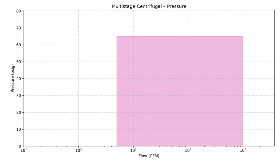
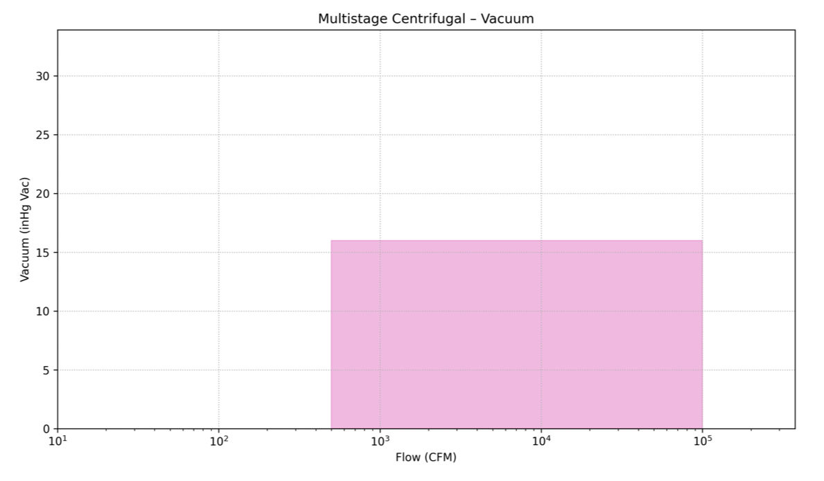
Multistage centrifugal blowers are capable of producing pressures up to 65 psig and vacuum down to 16” Hg. The flow range for a multistage centrifugal blower is from 500 cfm to upwards of 100,000 cfm.
Multistage Centrifugal (with Horizontally & Vertically Split casings) are commonly used in the following applications:
CAGI members who manufacture this product
Atlas Copco Compressors
Gardner Denver
Roots Blowers
Hibon/Ingersoll Rand
REGENERATIVE
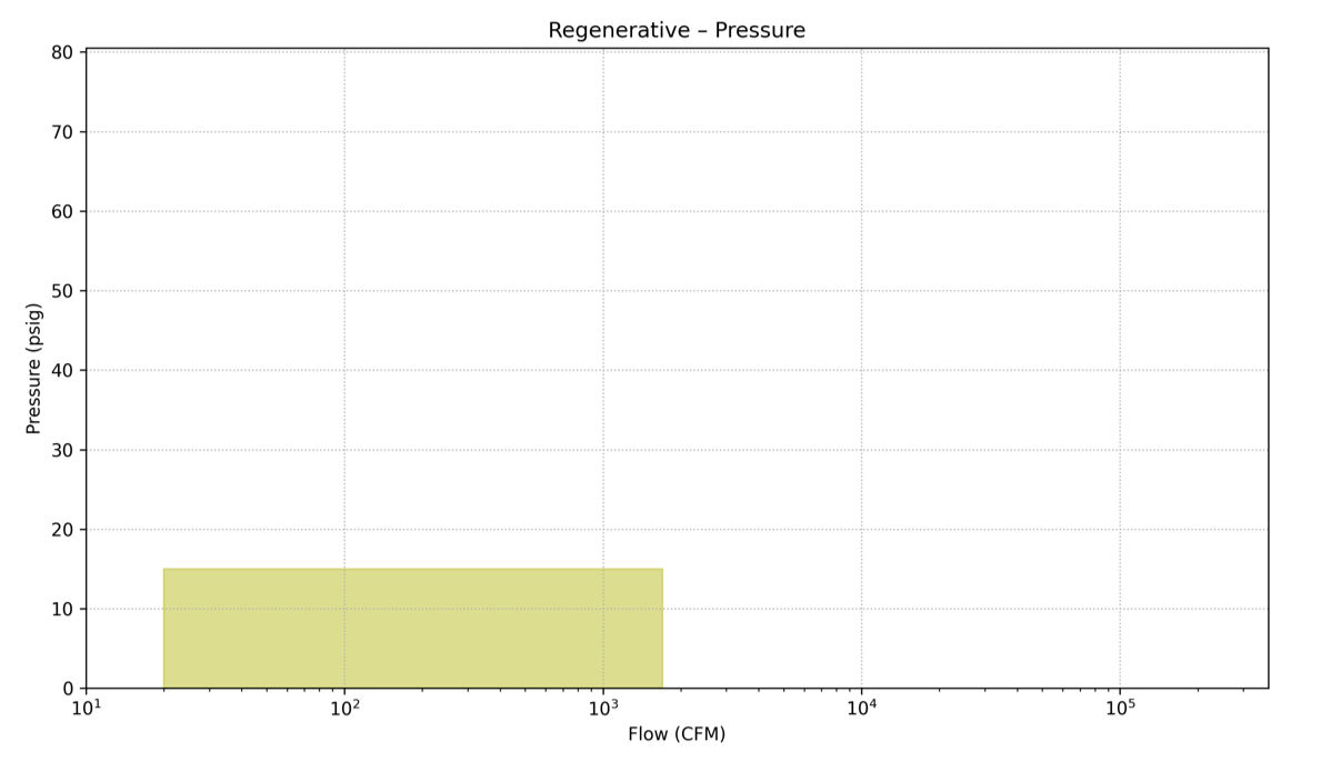
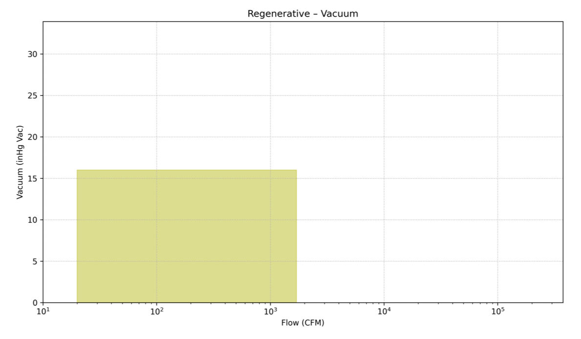
Regenerative blowers are used in applications ranging up to 15 psig service, with flows up to 1,700 cfm. Vacuum service up to 16 “Hg. This type of blower operates using one or two spinning impellers that are mounted directly on the motor shaft for contact free compression. As air or other gases enter the blower, the rotating impeller imparts velocity to the gas in the direction of rotation. Centrifugal force in the impeller blades accelerates the gas outward and the pressure increases. Every rotation adds kinetic energy, resulting in further increase of pressure along the side channel. The side channel narrows at the rotor, sweeping the gas off the impeller blades and discharging it through the outlet.
Some common names for regenerative blowers include regen, side channel, vortex and ring.
Regenerative blowers are typically compact in size, as motors are typically mounted integrally to the machine. They are relatively quiet in operation. Regenerative blowers are virtually maintenance free and less sensitive to ingested solids.
Regenerative blowers are limited on pressure and so there can be fluctuations in flow and efficiency with changes in pressure.
Regenerative blowers are commonly used in the following applications:
CAGI members who manufacture this product
Gardner Denver
Choose a blower type from the left-hand menu.
ROTARY LOBE
Rotary lobe blowers are positive displacement machines, commonly used for handling air or other gases up to 2 to 1 compression ratios, for either pressure or vacuum duty. These machines consist of two precision machined rotors which rotate opposite to one another, within an enclosed cylinder comprised of the housing (casing) and endplates. As each impeller passes the inlet opening of the housing, it traps a positive volume of air or gas and carries it around the housing to the discharge opening, where it is expelled.
The impellers are non-contacting, operating with minimal clearances. Impellers maintain these clearances through the use of timing gears. In addition, clearances between the impellers, housing, and endplates are held to very low values to minimize "back slipping" of the discharge gas to the inlet side, to optimize efficiency. Rotary blowers operate dry, without the need for a sealing fluid or lubricant within the process chamber. The impellers are commonly two-lobe, figure eight shaped, or three-lobe. Rotary blowers with two lobe impellers expel four pockets of air or gas per revolution, while units with three lobe impellers expel six pockets of air or gas.
Due to their operating principles, rotary blowers will see minor variations in flow compared to changes in differential pressure or vacuum. Typical operating ranges are from 2 to 15 psig under pressure duty, though designs are available up to 20 psig. In addition, units can be multi-staged for duty as high as 40 psig with interstage cooling.
For rotary lobe technology, vacuums to 15 inches Hg are typical, though models are available as high as 28 inches Hg. Variations in internal seal designs are available for use in non-air service, where leak tight operation is essential.
Rotary lobe blowers are commonly used in the following applications:
CAGI members who manufacture this product
Atlas Copco Compressors
Gardner Denver
Hibon/Ingersoll Rand
Roots Blowers
Kaeser Compressors
MD-Kinney
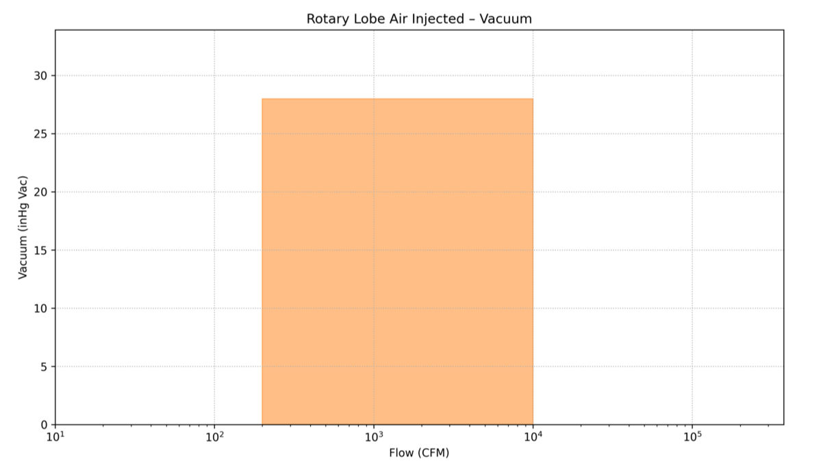
ROTARY LOBE AIR INJECTED
Single stage centrifugal compressors are variable flow machines commonly used for movement of air or other gases up to a 3 to 1 compression ratio for either pressure or vacuum duty. These machines consist of a single rotating impeller mounted within a casing which defines the gas inlet flow path, diffuser section, and discharge volute or collector area. The compression ratio capability of the compressor is primarily a function of the impeller peripheral speed and blade geometry. Impeller materials vary from aluminum, steel, and stainless steel depending on gas properties and rotational speed. Variations in shaft seal designs are available to suit gas being compressed.
Flow control may be accomplished by suction throttling, inlet guide vanes, discharge diffuser vanes, or speed variation. Each have their own advantages weighing initial cost against efficiency gains and control complexity.
Benefits of the single stage centrifugal compressor include high efficiency over a wide operation range. Delivered flow (and power consumption) can be reduced by nearly 50% without use of recycle or blow off lines. Delivered gas is oil and pulsation free.
Single stage centrifugal compressors are built for flow capacities ranging from 1,000 cfm up to 300,000 cfm. Initial cost of the low capacity machines may be higher than positive displacement type machines. However, in the medium to high capacity range, initial cost is generally very attractive.
Companies that manufacture this type of product:
Atlas Copco Compressors
Gardner Denver
Howden Roots
ROTARY SCREW/HELICAL SCREW
Rotary screw blowers, also known as helical screw blowers, function as low-pressure, oil free blowers (compressors) with discharge pressures up to 36 psig. The flows of rotary screw blowers are available from 20 cfm to 6,000 cfm and are available from a wide number of manufacturers. In vacuum service, the rotary screw blower can achieve vacuum levels as low as 22" Hg (v).
The rotary screw blower utilizes two intermeshing screws positioned parallel to each other inside a machined cylinder. The rotors consist of two separate precision-machined profiles: a male rotor and a female rotor. The male rotor rotates inside the cavity formed between the two flutes of the female rotor. The trapped cavity between the two rotors and the wall of the cylinder forms the compression chamber. As the rotors rotate, the trapped cavity propagates down the screw path of the rotors from the inlet to the discharge port. Unlike straight- or twisted-lobe blowers, where the airflow through the blower is perpendicular to the rotor shafts, rotary screw blowers have an axial airflow, parallel to the rotor shafts.
Rotary screw blowers have an internal compression ratio. Rotary screw blowers are typically machined to tighter clearances between rotors and housing than rotary lobe-type blowers, allowing for higher efficiency at a given compression ratio. Tighter clearances result in reduced slip (or blow-by), rotor deflection and operating temperature. Lower rotor temperature reduces thermal expansion and reduces the risk of rotor-rotor and rotor-housing contact during operation. Additionally, rotary screw blowers can achieve a higher compression ratio than rotary lobe in a single stage of compression.
Rotary screw blowers are commonly used in the following applications:
CAGI members who manufacture this product
Atlas Copco Compressors
Gardner Denver
Hibon/Ingersoll Rand
Kaeser Compressors
ROTARY CLAW
Rotary claw pumps are oil free, positive-displacement machines that can operate in pressure service up to 30 psig and vacuum service down to 24” Hg (v). The volumetric flow associated with this technology is generally 650 cfm or less. A rotary claw pump consists of two claw-shaped rotors. A drive rotor transfers power to the impellers through a set of timing gears, ensuring that the impellers do not contact each other. Extremely tight machined clearances allow the claws to maintain minuscule gaps between themselves and the cylinder during their rotation, minimizing slip. Similar to lobe-type and rotary screw blowers, rotary claw blowers employ oil lubrication for bearings and gears. Shaft seals keep the lubricant from entering the compression chamber and the high-pressure process air from pressurizing the gearcase.
Claw pumps typically are supplied as fully packaged units. Packages commonly include the claw air-end, integrated motor, inlet filter, and discharge silencer. By using variable speed motors, rotary claw blowers can be tuned to match a precise flowrate requirement. For flowrates in excess of 650 cfm, multiple claw airends can be operated in parallel.
Rotary claw blowers are commonly used in the following applications:
CAGI members who manufacture this product
Atlas Copco
MD-Kinney
ROTARY VANE/SLIDING
Rotary vane blowers are positive displacement machines that are available in oil free and oil injected designs. Oil free rotary vane blowers are typically used in pressure only service and have flows less than 400 cfm, with maximum pressure of 30 psig. Oil injected sliding vane blowers have flows up to 900 cfm with pressure capability of up to 24 psig with vacuum capability up to 28" Hg.
The rotary vane blower develops internal compression and utilizes both adiabatic and isochoric compression to generate system pressure. Accordingly, rotary vane blowers have efficiency and noise characteristics like rotary screw and rotary claw blowers. The rotary vane blower, also known as a sliding vane blower, consists of a housing, a rotor, and vanes as major components.
Rotary vane blowers are available as bare blowers. These types of blowers are often used in mobile transport industry applications for higher-pressure bulk material conveying and for vacuum-assisted onload and pressure-assisted offload of both bulk solids and liquids. For mobile applications, additional accessories are needed for a complete system. These accessories are oftentimes designed as a compact, fully packaged system for ease of installation on a truck chassis.
Rotary vane blowers are commonly used in the following applications:
CAGI members who manufacture this product
Atlas Copco Compressors
Fruitland Manufacturing
Gardner Denver
LIQUID RING
Liquid ring vacuum pumps (LRVP) work with a centrifugal liquid ring induced by an impeller offset in a pump housing. There is no mechanical contact between the moving parts, and the liquid acts like little pistons, allowing the machinery, in essence, to function like a conventional piston pump.
Upon activation, the rotor and liquid ring spins simultaneously. The rotor is positioned slightly eccentric to the center, thus dividing the liquid ring into cells. As these cells rotate, they create an airspace adjacent to the rotor’s center, and the liquid moves away from the rotor's hub, consequently producing a suction effect.
Conversely, when the cells pass the bottom, the movement redirects and forces the service liquid towards the hub, resulting in the expulsion of air from the segment—now filled with liquid and ready for a new cycle. To partition the suction and pressure sides, a flow plate and pump housing are strategically placed at the casing ends.
Continuous supply of liquid is required to compensate for the liquid discharge from the pump. In addition to providing replacement liquid, the liquid also cools the compressor gas in the pump and lubricates the mechanical shaft seals.
LRVPs can be supplied up to 2,000 HP with pressure capabilities up to 70 psig and vacuum levels down to 29.5" Hg. The flow range for LRVPs is from 100 cfm to upwards of 20,000 cfm.
Liquid ring blowers are commonly used in the following applications:
CAGI members who manufacture this product
Atlas Copco Compressors
Fruitland Manufacturing
Gardner Denver
MD-Kinney
SINGLE STAGE CENTRIFUGAL – INTEGRAL GEAR/EXTERNAL DRIVE
A single stage centrifugal blower is a variable flow type machine suitable for application in a wide range of gases including air up to a 3 to 1 compression ratio. The compression ratio capability is dependent upon the application conditions such as the gas being compressed, impeller tip speed, and blade geometry. A single stage centrifugal can be applied to both pressure and vacuum applications and for flows ranging from 1,000 cfm up to 300,000 cfm.
Single stage centrifugal blowers have a single radial impeller mounted within the casing. The impeller and casing materials will vary depending on the gas being handled and the pressure and temperature conditions. The application will dictate which shaft seal design is appropriate.
Single stage centrifugal blowers offer a wide operational range and can be adjusted for speed and other control features to provide high operational efficiency throughout this range.
The single stage centrifugal blowers are driven by electric motors or steam turbines. There is often a speed increasing gear required to drive the single stage impeller to the required design speed. The single stage designs that have an integrated gear box with the casing are known as integral gear.
Single Stage Centrifugal – Integral Gear/External Drive blowers are commonly used in the following applications:
CAGI members who manufacture this product
Atlas Copco Compressors
Roots Blowers
MULTISTAGE CENTRIFUGAL (WITH HORIZONTALLY & VERTICALLY SPLIT CASINGS)
Multistage blowers are available in two basic housing designs: vertically split and horizontally split. Both multistage designs compress a wide variety of gases including air through multiple stages of compression. The number of stages required depends on the applications compression requirements. The multistage centrifugal is a dynamic compression type machine providing variable flow at relatively constant pressure. The basic details of the two design are the following:
Horizontally split - The multistage design has a casing that is split on a horizontal plane through the centerline of the shaft with inlet and discharge connections cast integrally with the casing. The discharge and inlet connections can be arranged in the top half casing or the bottom half casing or one in the top half and one in the bottom half. Removal of the top half of the casing permits complete access for inspection or removal of the rotor and casing diaphragms. The bearing housings, bearings, and seals are horizontally split allowing complete access to the bearings and seals without removing the multistage unit from the installation. The bearings both radial and axial are hydrodynamic type allowing for long life and stable rotor dynamics. Pressure lubrication is required for the bearings. The lubrication system can be integral or console type. There are several seal options available to meet the requirements of the application specification.
Vertically split - The multistage is of a modular design with the casing vertically split to facilitate changing the number of compression stages to meet the operating requirements. The inlet and discharge locations can be located in a number of combinations to meet the customer’s needs. Standard offerings for this style of machines are anti-friction bearings with splash lubrication, although other options are available.
Multistage centrifugal blowers are capable of producing pressures up to 65 psig and vacuum down to 16” Hg. The flow range for a multistage centrifugal blower is from 500 cfm to upwards of 100,000 cfm.
Multistage Centrifugal (with Horizontally & Vertically Split casings) are commonly used in the following applications:
CAGI members who manufacture this product
Atlas Copco Compressors
Gardner Denver
Roots Blowers
Hibon/Ingersoll Rand
REGENERATIVE
Regenerative blowers are used in applications ranging up to 15 psig service, with flows up to 1,700 cfm. Vacuum service up to 16 “Hg. This type of blower operates using one or two spinning impellers that are mounted directly on the motor shaft for contact free compression. As air or other gases enter the blower, the rotating impeller imparts velocity to the gas in the direction of rotation. Centrifugal force in the impeller blades accelerates the gas outward and the pressure increases. Every rotation adds kinetic energy, resulting in further increase of pressure along the side channel. The side channel narrows at the rotor, sweeping the gas off the impeller blades and discharging it through the outlet.
Some common names for regenerative blowers include regen, side channel, vortex and ring.
Regenerative blowers are typically compact in size, as motors are typically mounted integrally to the machine. They are relatively quiet in operation. Regenerative blowers are virtually maintenance free and less sensitive to ingested solids.
Regenerative blowers are limited on pressure and so there can be fluctuations in flow and efficiency with changes in pressure.
Regenerative blowers are commonly used in the following applications:
CAGI members who manufacture this product
Gardner Denver
Compressed Air & Gas Institute
1300 Sumner Avenue
Cleveland, OH 44115
Phone: 216/241-7333
Fax: 216/241-0105
©2026 CAGI